|
|
||
|---|---|---|
| .. | ||
| README.md | ||
README.md
Quickly Start with Ubidots
In this qucik guide section, we will show you how to get the sensors data through Wio Terminal and then travel them to the Ubidots platform via Wi-Fi. We provide the tutorials for all the sensors in the kit, including the ones built in the Wio Terminal. Just a few clicks, you will get the value displayed on the Ubidots dashboard.
Materials Required
- Wio Terminal
- Grove - VOC and eCO2 Gas Sensor SGP30
- Grove - Soil Moisture Sensor
- Grove - Temp&Humi Sensor(SHT40)
- Grove - Vision AI Module
Materials Required
 |
|
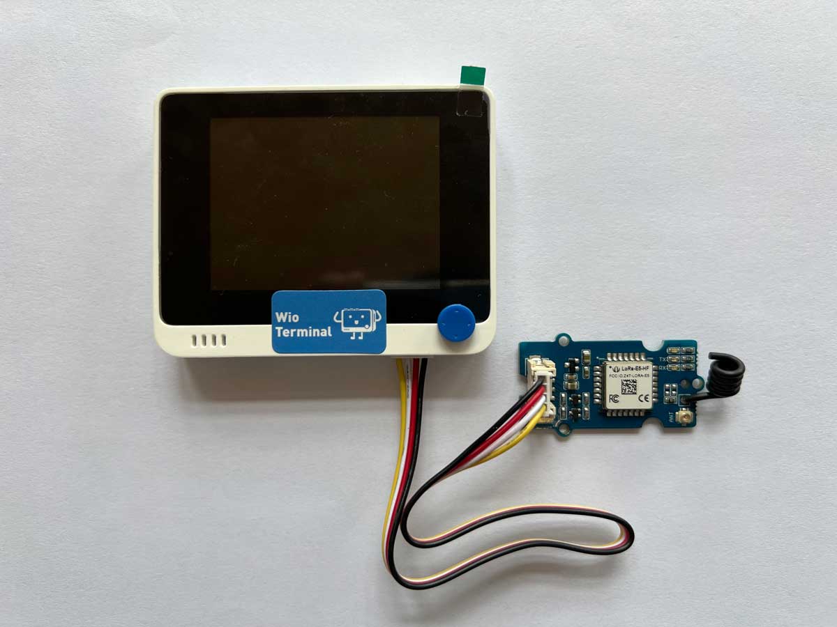
| Wio Terminal | Grove - Wio-E5 |
Preliminary Preparation
Before everything starts, we need some information to proceed our projects, including
- Wi-Fi SSID(Wi-Fi name)
- Wi-Fi Password
- Ubidots Token
- MQTT Client Name
And then we need to install the supported libraries.
Ubidots Account registered and Token Received
- Step 1. Sign into the Ubidots account.
- Step 2. Go to the user dropdown and click on API credentials. The API Key and Tokens can be both generated by a simple click.

MQTT Client Name
The MQTT Client Name must be unique where you can use the MAC address of the device, or you can simply generate with random ascii builder.

Connection
For Grove sensors in the kit, we need to configure the Grove port on the right side of the Wio Terminal as a soft serial port to receive data. And then we need to use Tpye-C cable to connect the Wio Terminal to the PC.
!!!Note Why not use the Grove port on the left? > The Grove interface on the left is IIC capable, and we use the IIC interface for most sensors, so keeping it is a better solution.
Software preparation
Step 1. You need to Install an Arduino Software.

Step 2. Launch the Arduino application.
Step 3. Add Wio Terminal to the Arduino IDE.
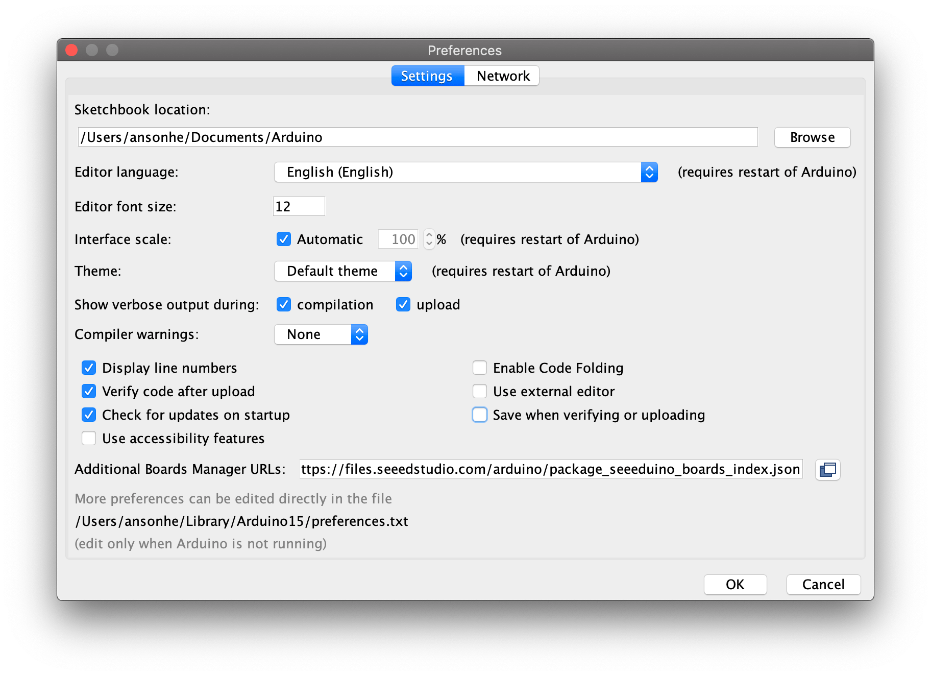
Open your Arduino IDE, click on File > Preferences, and copy below url to Additional Boards Manager URLs:
https://files.seeedstudio.com/arduino/package_seeeduino_boards_index.json
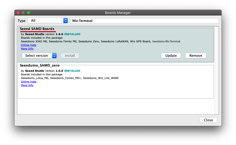
Click on Tools > Board > Board Manager and Search Wio Terminal in the Boards Manager.
Step 4. Select your board and port
You'll need to select the entry in the Tools > Board menu that corresponds to your Arduino. Selecting the Wio Terminal.
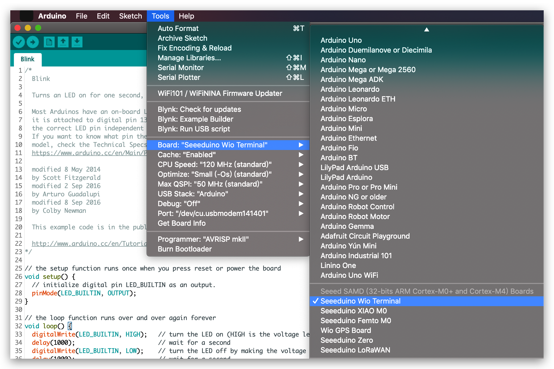
Select the serial device of the Wio Terminal board from the Tools -> Port menu. This is likely to be COM3 or higher (COM1 and COM2 are usually reserved for hardware serial ports). To find out, you can disconnect your Wio Terminal board and re-open the menu; the entry that disappears should be the Arduino board. Reconnect the board and select that serial port.
!!!Tip
For Mac User, it will be something like /dev/cu.usbmodem141401.
If you are not able to upload the sketch, mostly it's because Arduino IDE was not able to put Wio Terminal to bootloader mode. (Because MCU was halted or your program handling USB) Workaround is putting your Wio Terminal to bootloader mode manually.

<div align=center><img width=400 src="https://files.seeedstudio.com/wiki/Wio-Terminal/img/Wio-Terminal-Bootloader.png"/></div>
Step 5. Download supported Libraries
Visit the repositories and download the entire repo to your local drive.
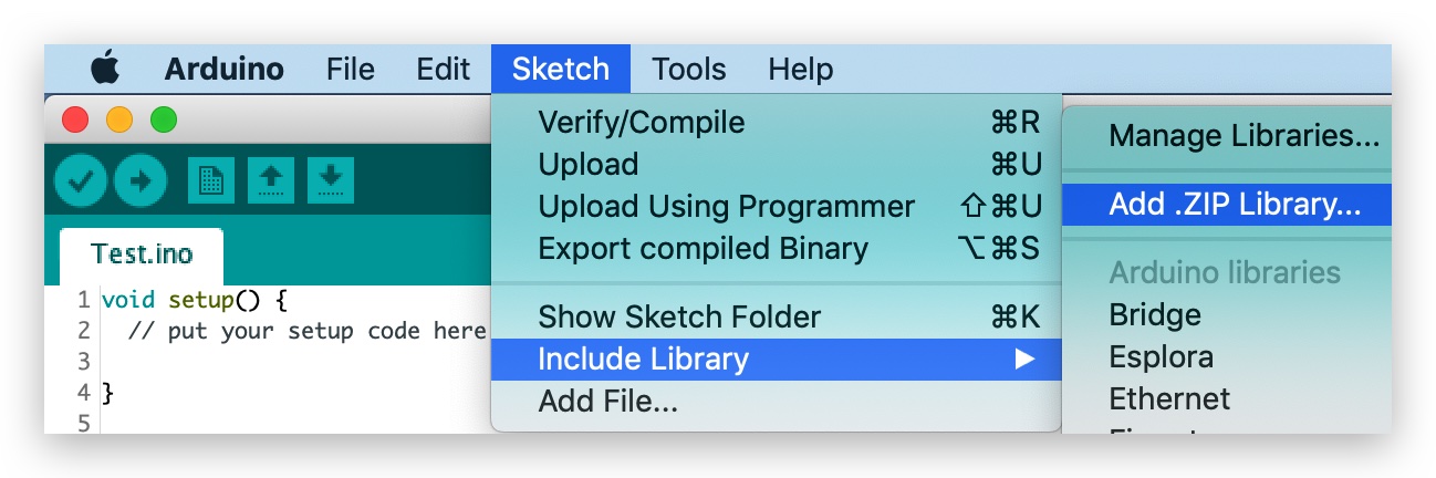
Step 6. Adding libraries to the Arduino IDE
Now, the libraries can be installed to the Arduino IDE. Open the Arduino IDE, and click sketch -> Include Library -> Add .ZIP Library, and choose the Disk91_LoRaE5 file that you've have just downloaded.
Built-in Light Sensor of Wio Terminal Traveled Data via Ubidots
The library we downloaded include all the examples that we can use in the SenseCAP K1100 kit. Naviagte File -> Examples -> -> and open it. Fill the information we generated before.
#define WIFISSID " WifiSSID (Wifi name)" // Put your WifiSSID here
#define PASSWORD "Wifi password" // Put your wifi password here
#define TOKEN "Your Ubidots Tokens" // Put your Ubidots' TOKEN
#define MQTT_CLIENT_NAME "MQTT client Name" // MQTT client Name
!!!Note
WIO_LIGHT is the pin for built-in light Sensor. The light sensor is connected to A13.
The light sensor is at the back of the Wio Terminal, just above the microSD card slot.

<td align="center"><div align=center><img width = 300 src="https://files.seeedstudio.com/wiki/K1100/20.png"/></div></td>
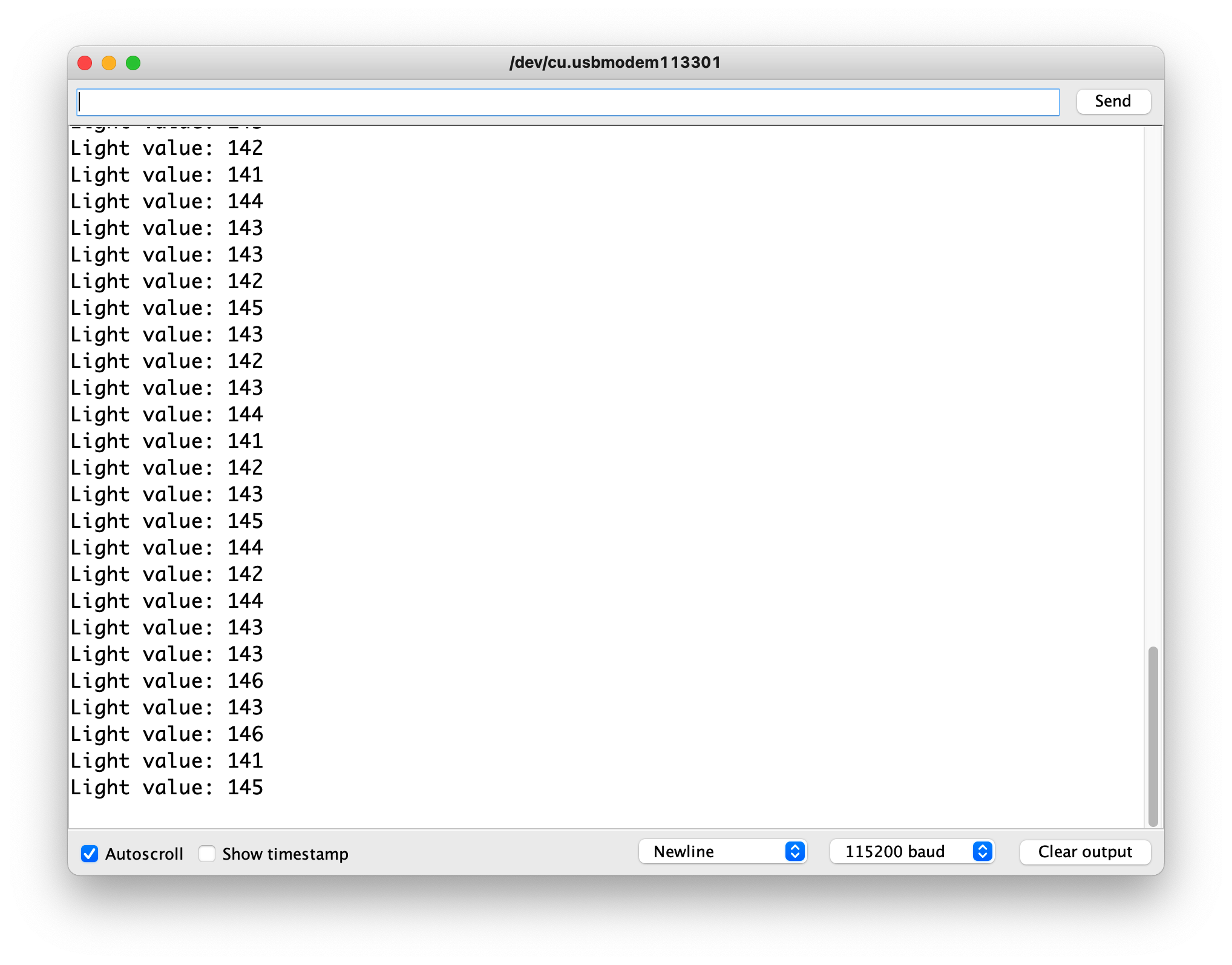
Open the serial monitor of Arduino IDE and select the baud rate as 115200 and observe the result.
Send data via Grove - Wio-E5
We combine the previous code of Grove - Wio-E5 to connect to the LoRa® network. Using the AT command it is possible to send the value of the light sensor to the LoRa® network.
As we know from the code in the section above to get the light sensor value, the light value obtained is an integer data of less than eight bits.
In this way, we determine the content, size and format of the data to be sent via the AT command. We might as well set up a large enough array, store the strings we need to send into the array, and finally use the send_sync() function to send the array out.
The pseudo-code for the above idea is roughly as follows.
......
  int light = analogRead(WIO_LIGHT);  //Get the Wio Terminal light value.

  static uint8_t data[2] = { 0x00 };  //Use the data[] to store the values of the sensors

  data_decord(light, data);

  if ( lorae5.send_sync(              //Sending the sensor values out
        8,                            // LoRaWan Port
        data,                         // data array
        sizeof(data),                 // size of the data
        false,                        // we are not expecting a ack
        7,                            // Spread Factor
        14                            // Tx Power in dBm
       )
  )
......
The rest of what we need to do is to use the begin() function to initialize Grove - Wio-E5 and the setup() function to configure the triplet information of Grove - Wio-E5. When we send a data message using the send_sync() function, we will try to join the LoRaWAN® at the same time, and once it succeeds, the data will be sent and information such as signal strength and address will be returned.
The full code example can be found here.
!!!Tip We do not recommend that you upload the code now to see the results, because at this point you have not yet configured Helium/TTN and will get a "Join failed" result. We recommend that you upload this code after you have completed the Connecting to Helium or Connecting to TTN chapter to complete the complete data sending process.
Once you have experienced and understood how the light sensor works and the data format, please continue with the next step of the tutorial join LoRaWAN®.
| Helium Section | |
|
Helium Introduction In this chapter, we will introduce the Helium console controls that we use to get a first impression of the Helium console. Jump to chapter > |
|
Connecting to Helium This section describes how to configure Helium so that sensor data can be successfully uploaded to and displayed in Helium. Jump to chapter > |
| TTN Section | |
|
TTN Introduction In this chapter, we will introduce the TTN console controls that we use to get a first impression of the TTN console. Jump to chapter > |
|
Connecting to TTN This section describes how to configure TTN so that sensor data can be successfully uploaded to and displayed in TTN. Jump to chapter > |


Tech Support
Please do not hesitate to submit the issue into our forum.
Statement
- The LoRa® Mark is a trademark of Semtech Corporation or its subsidiaries.
- LoRaWAN® is a mark used under license from the LoRa Alliance®.